Embedded development
Background
What is a Microcontroller?
A microcontroller can be thought of as a compact and low-powered computer. They run on a single chip and are used for specific tasks, such as reading sensors and controlling motors. A microcontroller utilizes pins to carry out operations. These are called General Purpose Input Output pins, otherwise known as GPIO pins. When using a microcontroller, it is important to know its GPIO voltage and current restraints. By not adhering to these constraints, we risk damaging the microcontroller (aka “frying it”). This means possibly melting internal circuitry and shorting input/output pins.
Microcontrollers vs Microprocessors
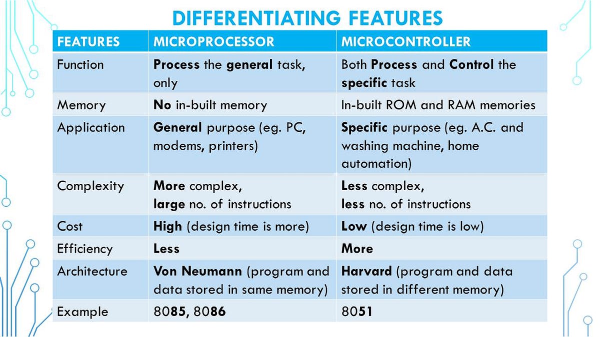
One mistake many make is confusing microprocessors for microcontrollers and vice versa. While they may sound similar in name, they are different in nature. A microprocessor is a general purpose CPU that requires external memory and peripherals(these are other hardware components). On the other hand, microcontrollers have processors, memory, and peripherals. They both have their own place where one outperforms another. The table below from Dr. Urvashi Singh’s Introduction to Microprocessors and Microcontrollers does a great job showing the difference.
Skills and Protocols
Before you start using microcontrollers, there are a couple things that are beneficial to know beforehand. If you have prior C/C++ experience, you’re in great shape to start, but don’t worry if you don’t, we have a C/C++ guide you can learn from. It would most definitely be helpful to familiarize yourself with how to create a circuit and know what to look out for and know how to they work. Most microcontrollers are coded using C/C++ but some are also coded using Java, Python, Rust, and other languages.
Overtime, you’ll learn about protocols such as I2C, SPI, and UART. Protocols like these determine how the microcontroller shares and utilizes data from peripherals(such as sensors as you may recall). However, we’ll get to that later.
Number Systems
You may be wondering, why do I have to learn about number systems to code a microcontroller? Microcontrollers, FPGAs, and circuits all require a basic knowledge of them. Numbers are the basis to how a computer works. This mainly applies if you’re coding in C or C++, if you’re using JS then feel free to skip this section. It’s still something we would reccommend you learn, but it doesn’t take top priority.
Technically speaking, microcontrollers use base 2, base 10, and base 16, known as binary, decimal, and hexadecimal respectively. Microcontrollers store data in binary, where the 0s and 1s are bits and can be used to interpret voltages. Hexadecimal is used for memory maps, registers, and memory addresses. Both are essential for digital logic and circuits in general.
Binary
We’ll start off learning about binary. The decimal system is probably the one you think of using when you count, and we can use this for binary. Base 10 means that there are 10 digits being used to represent the number, which culminates in making groupings of tens. Binary will use just 2 digits, 0 and 1. How do we convert from these two systems then?
Decimal to Binary
To convert from base 10 to base 2, the simplest method is to use divison. This means dividing the base 10 number by 2 repeatedly while recording the remainder, using the quotient as the new dividend while 2 remains the constant divisor until we get a quotient of 0 and some remainder. The binary number will be the remainders from the last to the first. Here is an example from Wendy Qui’s AP Computer Science lesson:
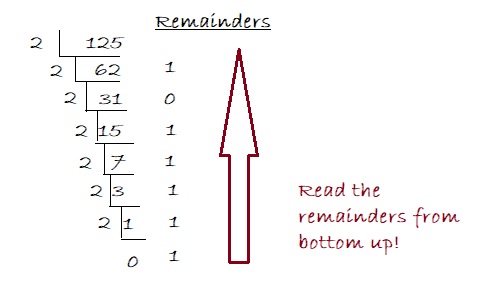
Therefore, 125 in decimal is 1111101 in binary.
Binary to Decimal
To convert from base 2 to base 2, the simplest method is to use the positional value method. This means going from the least significant bit(LSB), which will be the number in the right-most place, to the most significant it(MSB) and assigning it a power of 2, always starting from 0 being the LSB. We multiply the bit by this power of two, and sum all of the bits till we get our decimal number. Here is an example from Geeks for Geeks:
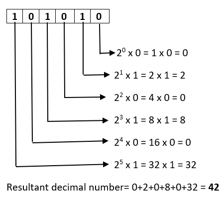
Therefore, 101010 in binary is 42 in decimal.
Hexadecimal
Hexadecimal is as aforementioned, base 16. It’s important, as is binary, for configurations of GPIO. Usually, there are functions that you can use or create as a shortcut, but it’s definitely something that you should have a background in.
Hexadecimal and Decimal
Before we learn to convert between them, let’s establish the “digits” we’ll be using. Hexadecimal will need 16 digits, just as decimal needs 10 and binary needs only 2. However, we only have 10 numerical digits, so where are we going to get the other 6? We utilize the first six letters of the alphabet (their uppcase forms). This means that A = 10, B = 11, C = 12, D = 13, E = 14, and F = 15.
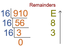
Suppose we have the number 100 in decimal. To convert this from decimal to binary we would do a similar process as if were going from decimal to binary. We consecutively divide 100 by 16 whilst recording the remainders, and we keep going until we get a quotient of 0.
This image from MAD for MATH demonstrates this well:
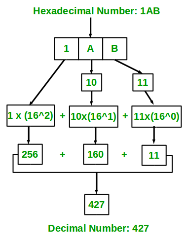
To go from hexadecimal to decimal, we would do a similar process as when we convert from binary to decimal. We take the hexadecimal number, and starting from the right-most digit, assign it a value starting from 0. We then multiply the digit by 16 to the power of whatever number we assigned that digit. We add these values up to get the number in decimal.
This graph from GeeksforGeeks is a great visual:
Hexadecimal and Binary
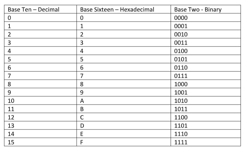
Binary and hexadecimal actually have a very close relationship. One hexadecimal character can represent four bits. Let’s take 15 in decimal for example. In binary, this would be 1111. In hexadecimal, this is just F. We can do this for every digit in a hexadecimal number. For instance, let’s take the number 10 in decimal. This is A in hexadecimal, and we can represent this as 1010 in binary.
Here is a table from a Kvaser developer forum for the rest of the numbers:
Let’s look at a larger number. Suppose we have the number A3F8 in hexadecimal. Each digit can be represented in four bits, so let’s go from the right-most digit.
8: This would be 1000 in binary.
F: This would be 1111 in binary.
3: This would be 11 in binary. However, we will consider this 0011. When converting from hexadecimal to binary, if we have leading 0s, we don’t take them out.
A: This would be 1010 in binary.
Therefore, the hexadecimal number A3F8 would be 1010001111111000 in binary.
If we wanted to go from Binary to Hexadecimal, we would divide the binary number to groups of four digits, and essentially do the process in reverse. For example, if we have 1010001111111000, then we would divide this into 1010 0011 1111 1000. We always start from the right and go to the left when making these groups.
1000: This would be 8 in hexadecimal.
1111: This would be F in hexadecimal.
0011: This would be 3 in hexadecimal.
1010: This would be A in hexadecimal.
Therefore, the binary number 1010001111111000 is A3F8 in hexadecimal.
C Variables and Operators
At this point, we’ll start actually applying what we’ve learned about number systems and such. However, we already have a guide on this! So for the sake of not being redundant, I’ll reference you to the C/C++ guide once again. Make sure you know this well, I would recommend using either Code Composer Studio or Visual Studio Code as an IDE. However, if you’re already more comfortable using another IDE, please don’t hestitate to use that instead. Here are the guides for installation if you don’t have it:
Visual Studio Code Installation
Code Composer Studio Installation
Basic Circuits
We’re finally at the circuitry part! Microcontrollers aren’t just code, they integrate circuits as well. Here we’ll be going over some circuit basics as well as information on the GPIO. It’s important to be careful when designing and implementing circuits since we risk harming the microcontroller (there’s no coming back from that, and if there is it’s a lot of work). It’s better to measure twice and cut once when doing this.
Circuits work by making connections from components to create a path that electrons flow through (aka electricity). You’ll usually need some sort of power source, wires to make the connections, and components. A circuit works when the connections are all closed (think of this as a loop). You’ll need a grounded part as well. When deciding on a power source, consider the limits of the microcontroller to avoid overbearing it. We could talk about circuits for days, so for a quick overview, look at this guide from Geeks for Geeks. It’s best to study LEDs, resistors, voltmeters, and ammeters. The rest you’ll learn later.
GPIO
I referenced GPIO earlier in the guide. These input/output pins is how information is sent to the micrcontroller, the form of which being different voltages. Sometimes we’l use them to read voltage levels, and sometimes we’ll use them to look at signals. This let’s the CPU and external components communicate.
Configuration
There are a couple different modes that you can set the GPIO to. These include as an input or an output. Some pins have an alternate function functionality that you can set the pin to instead.
Pull-up/Pull-down Resistors
In our opinion, something that’s super important to know about before you start is the function of pull-up an pull-down resistors. This prevents harm to the microcontrollers, as well as create a voltage differential. Pull-up resistors are used to make a voltage difference btween the power supply and the pin, while pull-down resistors make voltage differences between the pin and ground.
Digital logic circuits have only three states. They can be high, low, or floating, which is when the pin is not high or low. The microcontroller has unpredictable behavior when it comes to a floating pin, which is why it’s best to has a resistor that can pull the pin to either high or low.
Applications
They can be implememented when adding components such as buttons or switches, to make sure that the microcontroller gets a clean button press. They are used with digital gates, sensors, and when using analog to digital conversion of signals in general. They are also used on the I2C protocol bus, so that it can act as an input or an output.